
This article is intended to familiarize the reader with the functions, design, and characteristics of the crystalline waveplate – a true workhorse in precision optics.
The crystalline waveplate is an essential and versatile tool for controlling, analyzing, and optimizing polarized light. Whether the goal is to separate or fine-tune wavelengths, adjust ellipticity, or rotate polarization, the right waveplate can do the job in very little space. This simple plane-parallel optical device is economical, handles high pulse and continuous powers, and is available in stock or in custom configurations.
In form, a crystalline waveplate consists of one or more plane-parallel plates of birefringent material, usually synthetic crystal quartz. In use it shifts the phase of light polarized along its optic axis with respect to light polarized across its optic axis. This results in the transformation of one state of polarization to another – linear to circular, vertical to horizontal, etc. In conjunction with other polarizing elements such as Brewster windows, polarizing beamsplitters, and linear polarizers, the waveplate can act as a valve, filter, tuner, or switch.
Typical applications
- In lasers, wavelengths are combined and separated, extremely high pulse powers are achieved through Q-switching, and destructive feedback is quenched.
- In industrial laser cutting systems, cleaner and more uniform cuts are achieved with circular polarization
- In surgical and industrial multi-axis beam delivery systems, power losses and variability are minimized by polarization control
- In telecom, scores of wavelengths in a single fiber are multiplexed and routed by devices incorporating waveplates.
- In microscopy, sub-wavelength height features are displayed in vivid color.
- In biology and mineralogy, specimens can be analyzed according to their action on polarized light of different colors, revealed by waveplates.
- In brewing, sugar content can be determined by the degree of polarization rotation.
- In rangefinders, strong output pulses are isolated from weak returns.
- And many others.
A very brief review of polarization states and birefringence
Completely polarized light can be described by the projection of its transverse vibrations onto a plane defined by two arbitrary orthogonal axes (we can call them X and Y) and the time phase difference between these two projections. If the light is completely polarized within one plane, we call that plane-polarization or linear-polarization. If the X and Y axes are at an angle to this plane we use Cartesian coordinates to describe the projected components, which may be of different amplitude.
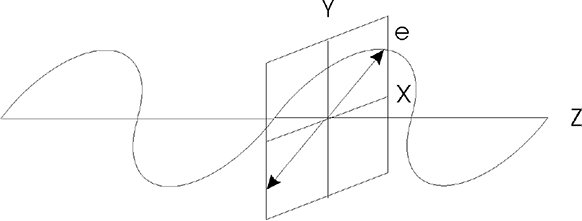
Figure 1: Representation of linear polarization projected onto an arbitrary transverse plane
A phase difference of a half-wave (180° or π radians) between the X and Y components mirror-reflects the plane of polarization about the X or Y axis. If the phase difference is any other value, the light is not contained within a plane and its projection describes an ellipse over time on the X-Y plane. We call this elliptical polarization. Circular polarization is a special case of elliptical polarization. Elliptical and circular polarization can have a clockwise or counterclockwise sense.
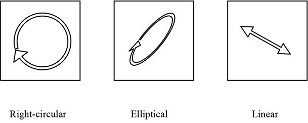
Figure2: Polarization states viewed looking into the beam.
Birefringent materials exhibit a different index of refraction for different orientations of polarization. Crystal quartz, in particular, has a difference of about 0.009 between its ordinary (o) and extraordinary (e) indices. When light incident on quartz has components seeing both indices, those components will propagate at different velocities and fall progressively out of phase.
Waveplates are made with the optic axis (c or z) in the plane of the surface so that birefringence is maximized. Phase differences of any integral numbers of wavelengths are not discernable, but as explained earlier, fractional wavelength phase differences transform polarization states.
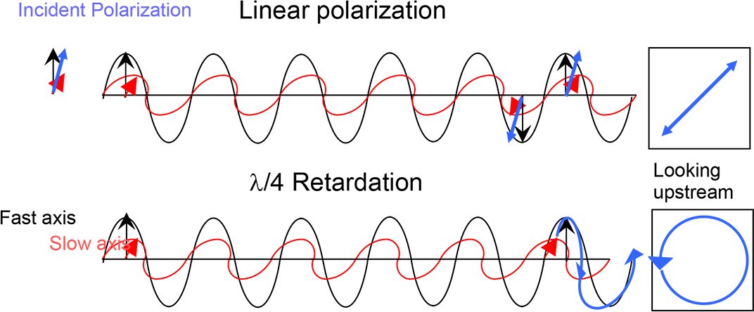
Figure 3: One quarter wave of retardation of X component with respect to Y.
What are P and S polarization?
These are not strictly polarization states, but rather special cases of the orientation of a linear polarization state with respect to a reflecting or refracting surface. The plane of polarization contains the e-vector without regard to surfaces. The plane of incidence contains the directions of propagation and the surface normal without regard to polarization. P-polarization is where those two planes are parallel. S-polarization is where those two planes are perpendicular. A convenient way to remember these cases (for those unfamiliar with the German language) is to imagine the plane of polarization as the plane of a playing card brought into contact with the optic’s surface. In the P-orientation the card’s corner will ‘poke’ into the surface; in the S-orientation its end face will ‘slip’ across the surface. Alternatively, imagine the plane of polarization as the plane of a flat stone thrown into a lake. In the S-orientation, it will ‘skip’ across the lake; in the P-orientation it will ‘plunge’ into the lake.
The waveplate in a nutshell
Say we have linear polarized light with its plane of polarization bisecting the X and Y axes. The X-component and Y-component are equal and in phase. Now we insert a quartz waveplate whose e axis is along X. Because ne is larger than no in quartz, the X-component falls behind the Y-component inside the waveplate, and exits out of phase.
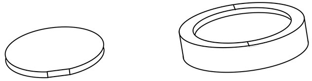
Figure 4: Circular waveplate with fiducial flat (left) and mounted in cell with scribed orientation marks. The z axis is along the diameter containing the flat or the scribe marks.
Sleight of handedness
If that phase difference (δφ) is any odd multiple of a quarter-wave, the exiting polarization becomes circular. If instead we insert a waveplate at the same orientation whose δφ is an odd multiple of λ/2, the exiting polarization is linear but orthogonal to the input. Now if we rotate that half waveplate (λ/2) so that its slow axis is no longer along X, we obtain linear polarization with an orientation mirrored about the waveplate’s axis. Thus a λ/2 waveplate can rotate linear polarization to any desired orientation. And if we rotate the quarter waveplate (λ/4), we obtain elliptical or linear polarization. And all of these transformations can be done in reverse!
Characteristics of waveplates
Birefringence is neither exactly proportional to wavelength nor completely achromatic. Therefore a λ4 waveplate at 600 nm is not a λ/4 waveplate at 300 nm, nor is it a λ/2 waveplate at 300 nm. This creates both limitation and opportunity: If we want to route two wavelengths simultaneously, we utilize a waveplate that functions differently at the two wavelengths. Also, temperature affects not only expansion and therefore waveplate thickness, but also its birefringence. Angle of incidence also affects retardation. And each birefringent material has different characteristics. Only certain options are available, and some work better than others, so it is critical to discuss your requirements with a leading firm specializing in waveplates.
Multiple order waveplates
The simplest waveplate is a single plate of synthetic crystal quartz with retardation between 20 to 80 quarter-waves. Why so many quarters? A 1λ/4 quartz waveplate at 500 nm would be only 67.7 µm thick, nearly impossible to handle, clean, mount, or even fabricate. A 9.25 λ plate is almost 0.5 mm thick: a practical compromise all around – unless it must also work across 488-512 nm. Across that range this plate changes from nearly zero effective retardation (9.00 λ) to over λ/2 (9.505 λ.)
What does Zero Order mean?
Fractional waves of retardation are detectable; full waves aren’t. So what distinguishes a 1λ/4 waveplate from a 37λ/4 waveplate? As we’ll see there are important advantages either way. Clearly the 37λ/4 plate is a higher “order,” but what is an order?
Regrettably there is no standard. Some people count the first instance as “first order.” Thus 1λ/4 would be a first order. Others count a full wave as an order. Thus 5λ/4 would be a “first order.” Still others count the total number of functional units: 5λ/4 would be a “fifth order.” And some count the number of units with similar function: 5λ/4 would be a “third order” because the “first” order is 1λ/4, 2λ/4 acts not as a quarter wave but a half wave retarder, 3λ/4 acts as a quarter wave retarder (although of opposite handedness) and 4λ/4 does nothing. To make matters worse, the desired retardation is not always modulo λ/4. What order is a 5 3/8 λ waveplate? Or an 8.4 λ waveplate?
So what is a “zero order?” Good question. In this article we use the term “zero order” to mean less than 1λ. The only safe way to avoid confusion is to specify the total retardation, for example, 7.25 λ.
Dual-wavelength waveplates
Any multiple order plate will exhibit desirable retardation values at more than one wavelength. The plate described above, designed to be 9.25 λ at 500 nm, will be exactly 11.25 λ at 420.9 nm, 8.5 λ at 539.6 nm, etc. Unfortunately we don’t pick wavelengths, they pick us. And finding a useful combination at two or more specific wavelengths is a bit of art. Some combinations are closer matches than others, and some are impractically thick or thin. A knowledgeable applications engineer will find a workable combination if it exists. It never hurts to ask.
Figure 5: Retardation within a dual-wavelength waveplate. Thickness increases to right. The respective retardations of two wavelengths are depicted by differently colored lines representing quarter-waves. Two useful combinations of those wavelengths match well at the thicknesses indicated.
Dual-wavelength waveplates with different fractions at two chosen wavelengths enable selective processing of the beams: One wavelength may be circulated while the other is selected out, one may be rotated while the other is not, etc. Laser and instrument designers find these functions invaluable. It is even possible sometimes to find useful combinations for three wavelengths.
Compound zero order waveplates
If two identical multiple order plates are placed together so that one’s fast axis is along the other’s slow axis, they cancel each other’s retardation. But if those two plates differ in retardation by 1λ/4, the function is similar to that bubble-thin true zero order plate. Compared to the 37λ/4 multiple, the variation of retardation vs. wavelength and temperature are reduced by the ratio 37:1. Retardation change vs. angle of incidence, however, is proportional to the overall thickness.
Figure 6: Comparison of multiple and zero-order retardation vs. temperature
Figure 7: Comparison of multiple- and zero order retardation vs. wavelength
Figures 6 and 7 clearly demonstrate why compound zero-order waveplates are frequently preferred despite their somewhat higher cost: They maintain optimum performance across a much larger range of temperatures and wavelengths. For use with laser diodes having variable wavelength, or in instruments that warm up over time, or in locations subject to the environment, their stability is paramount.
Achromatic waveplates
We can combine multiple order waveplates made from two different birefringent materials to achieve achromatic compensation across a broad spectral range. The design process is similar to making an achromatic doublet lens, although we have far fewer materials to choose from. Useful achromats can be made with combinations of quartz, MgF2, and sapphire. A quartz-MgF2 achromat maintains 0.250 ± 0.003 λ from 700 to 1000 nm. Tower Optical offers three such ranges: 465-610 nm, 700-1000 nm, and 1200-1650 nm
Construction of achromatic and compound zero-order waveplates
The two components comprising these waveplates must be mutually aligned to work properly. This can be accomplished in several ways: Optical contacting the two parts, cementing them, or co-mounting them separately to a cell with an air-gap between.
Optically contacted waveplates
Optical contacting is a technique whereby two extremely clean, matching surfaces are brought into intimate contact and bond to each other through the mutual attraction of Van der Waals forces. Beam deviation and transmitted wavefront are preserved. Because differential expansion can build stresses within the bond to the point that the parts separate, contacted waveplates – especially large ones – should be protected from extreme temperature excursions even during storage and shipment.
Cemented waveplates
Clear optical cement can be used to bond the two components. This technique produces greater durability across the cement’s usable range (typically -30 C to + 80 C.) However, beam deviation is usually degraded to several arc minutes, λ/10 transmitted wavefront tolerances are more difficult to achieve, and laser damage threshold and power handling are severely compromised within the cement layer. Still, this option is useful in extra-cavity, low-power situations where ruggedness is a priority.
Air-gap waveplates
By separating the two components, the problems of the interface are avoided. Air-gap waveplates exhibit especially high laser damage threshold, extreme temperature range survivability, and good vacuum operation characteristics while maintaining the best beam deviation and transmitted wavefront. This option is slightly more expensive because both sides of each component must be coated to avoid reflective losses.
Coatings
Uncoated synthetic crystal quartz has practically zero absorptance across from the UV into the near IR.. While contacted and cemented surfaces have essentially zero reflectance, non-immersed surfaces incur a Fresnel reflectance loss of about 4.65% each. To preserve power and avoid interference losses and laser feedback, anti-reflective (AR) coatings are advised for all non-immersed surfaces.
Single- wavelength anti-reflective coatings (VAR) reduce reflective losses to under 0.15% per surface when tuned to the wavelength of use. Dual -wavelength or dual- band (DBAR) coatings are necessary for dual-wavelength waveplates, and broad-band (BBAR) coatings for achromatic waveplates.
Other types of retarders
Polymer waveplates have some desirable qualities including true zero order operation, broad field of view, and large apertures. On the other hand they have a low damage threshold unsuitable for intracavity or high power laser use, and limited storage temperature range.
Mica waveplates are inherently zero-order, have very low dispersion and broad angular tolerance, and can be made inexpensively. Because of their low dispersion they can make (λ/4, λ/4) and (λ/2, λ/2) combinations at harmonic wavelengths, but not other combinations. And they can only be made by cleaving from natural mica which results in larger retardation tolerances and localized defects, and they have a very low damage threshold and high absorption.
Glass rhombs and prisms such as the Fresnel rhomb and its variations are extremely achromatic, quite insensitive to temperature variations, and have low sensitivity to angle of incidence. On the other hand they have a limited field of view, are expensive, very long (≈ 4 times the aperture for λ/2 and ≈ 20 times the aperture for a non-offsetting λ/4), require large lateral clearance (≈ 4 times the aperture plus mounting for the shorter designs) and may offset the beam (the shorter λ/4 offsets the beam by 1.3 times the aperture.)
Crystal quartz waveplates offer the lowest beam deviation (<1 arc second,) the best transmitted wavefront (<λ/10,) a small package, high damage threshold, and the option of multiple-wavelength combinations, at a reasonable price. On the other hand they do have a limited field of view.
Crystalline waveplates’ field of view
Because their retardation depends upon path length and birefringence, and the optic axis is in the plane of the surface, angle of incidence affects retardation. Waveplates are typically designed for best performance at normal incidence. Light incident at an angle rotated about the optic axis experiences a greater path length, while light incident at an angle to the optic axis normal experiences a lower birefringence. Therefore light incident non-normal to the optic axis is retarded less, and light incident at an orthogonal angle is retarded more, than nominal. The difference is proportional to the overall thickness of each plate, its inherent birefringence, and the square of the angle to each axis taken separately. Thus doubling an angle quadruples the effect, in opposite sense in two orthogonal axes, while light in a plane that bisects the axes sees practically no effect. Crystalline quartz and MgF2 are both positive uniaxial crystals. A compound zero-order or achromat made from these materials exhibits an angular dependence of retardation equivalent to the sum of the separate parts. This effect can be reduced in two ways: Thinner parts overall (for multiple or compound zero-order,) or an achromat made from a positive and negative pair such as quartz and sapphire
In collimated light this effect can be utilized to angle-tune the waveplate, obtaining the exact desired retardation regardless of manufacturing variations. However in uncollimated light this effect can deny the desired performance. If possible, keep divergence and angle of incidence below 30’. Again, the guidance of a knowledgeable product specialist is invaluable.
Which is the “slow” axis?
You had to ask! This can be confusing. For purposes of quartz and MgF2 waveplates,
Light polarized along the optic axis goes slower (is retarded.)
The situation is reversed for sapphire whose ne is lower than n0.
Light experiences the extraordinary index of a crystal when it is polarized along the optic (z) axis. In a waveplate, the optic axis is in the plane of the surface and perpendicular to the propagation, allowing light to be polarized either within or across the optic axis.
But light propagating along the z axis, being a transverse wave, is always polarized perpendicular to the z axis and so it propagates faster. This is not how waveplates are used, and is the cause for some confusion.
The z axis is indicated on circular waveplates by a small edge flat. The z axis runs from the center of that flat across the diameter.
Checklist when specifying crystalline waveplates
To ensure best performance, specify as follows:
- Desired retardation including whether zero or multiple order, and the integer multiple if important
- Nominal angle of incidence (preferably normal) and its orientation to the c-axis if not normal
- Desired retardation including whether zero or multiple order, and the integer multiple if important
- Field of view
- Temperature ranges: shipping, storage, and operation
- Wavelength(s) and ranges
- Power
- Clear aperture
- Special environmental considerations such as vacuum operation or pressure
- Whether the waveplate will be cemented or immersed during subsequent assembly
If uncertain about any element of waveplate design, discuss your requirements with a knowledgeable product specialist who can provide the guidance you need.